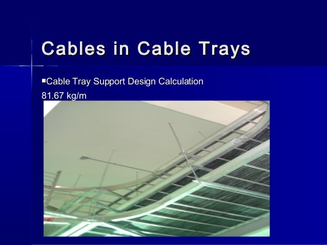
Cable Tray Support Design Calculation

Cable Support Systems Design And Installation Ee Publishers
Http Www Sourceiex Com Catalogs Chapter 2014 20cable 20support 20systems Pdf

Cable Trays Nema Classifications Unistrut Service Co

Cable Tray Raceway Fill And Load Calculations Electrical Engineering 123

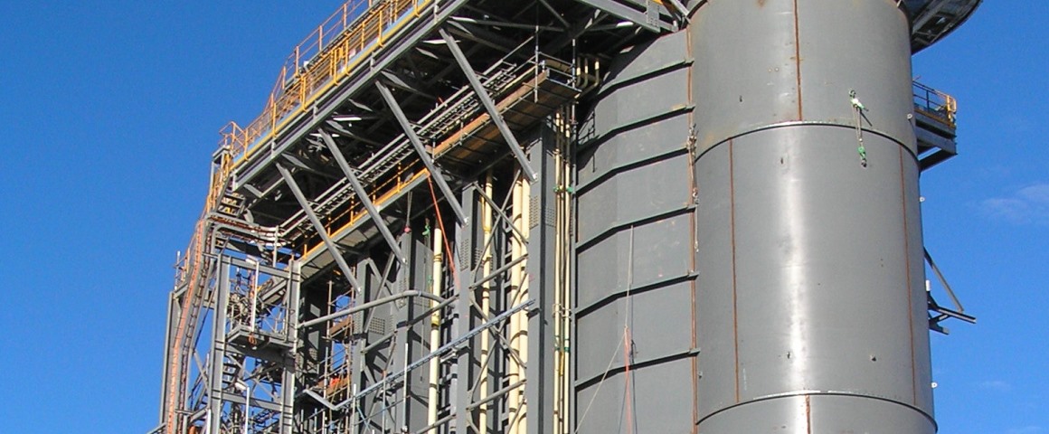
Typical Design Philosophy Of Cable Trays For Power Plant Electrical Engineering 123

Cable Tray Design Guide Ebsp
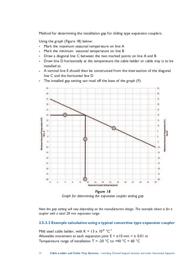
To join two components together clamp or fix to walls ceilings or other supports covers and cable retainers associated supports bespoke supports for cable tray and cable ladder other than bs 6946 channel.
Cable tray support design calculation.
Cable Tray Safe Working Load Test Swl Electrical Safety

Structured Cabling Installation Practices Part Three Installing A Structured Cabling System Dintek Articles Dintek Electronic Ltd

Cable Tray Installation Details With Pictures Paktechpoint

Cable Tray Size Calculation Cable Tray Size Techengineer Youtube
Cable Sizing Software Cable Sizing Calculation Etap

Cable Tray System Design Youtube
Conduit Or Cable Tray Ec M

Cable Size Calculation For 350 Kw Ht Motor Chart And Table Cable Tray Cable Chart Electrical Cables

Cable Tray And Conduit Sizing Excel Sheet Free Download Cable Tray Cable Excel
Cable Penetration In Kgp Substations

Pipe Racks An Overview Sciencedirect Topics
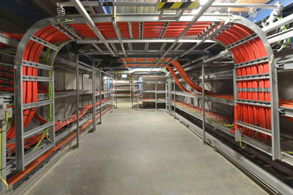
Guidelines For The Installation Of Cable In Cable Trays The Ef

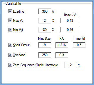
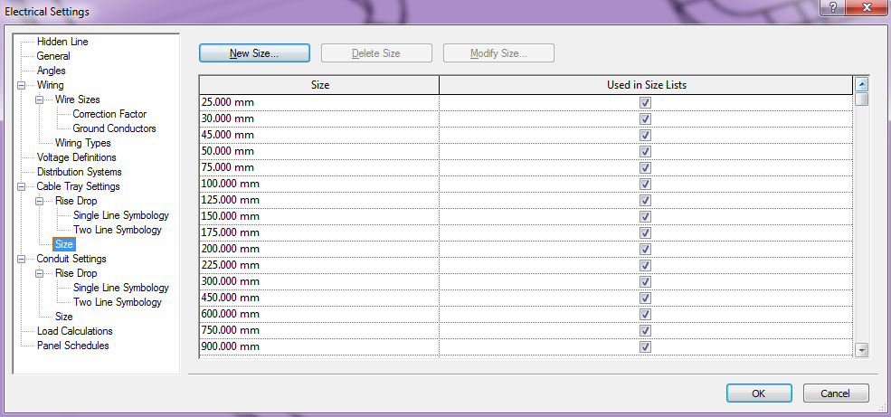
Other Settings
Electrical Raceway And Cable Routing Cad Design Software Paneldes

Easy Step To Make 45 Degree Offset Cable Tray Pipe And Air Duct Youtube
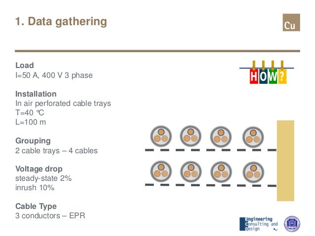
Principles Of Cable Sizing
Beama Best Practice Guide To Cable Ladder Cable Tray Systems
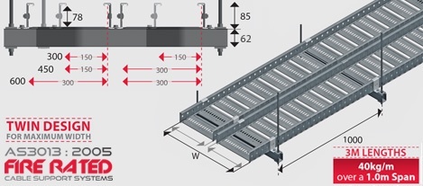
Fire Rated Cable Tray 600mm W X 3000l 40kg
Https Encrypted Tbn0 Gstatic Com Images Q Tbn 3aand9gctuksd Ebxog3081izgmiq3vxydb3tnh06osnyl F09g0kgqnny Usqp Cau

Cable Tray Mechanical Support Systems
Http Nalp Com Wp Content Uploads 2016 10 Eaton Bline Cable Tray Pdf
Electrical Modelling Operation In Revit Modelical
Https Www Asu Edu Purchasing Bids Pdfs 341901 Attach 4 Pdf

Safety And Health Information Bulletins Safely Installing Maintaining And Inspecting Cable Trays Occupational Safety And Health Administration
Source : pinterest.com
